
Attribution: This is a cached copy of a third party project. Many of these sites are from 20 years ago and the majority are no longer running. We show only the first page of the project. We do not save all pages since copyright belongs to the third-party author.
Decimal to BCD Convetor
Email Ron
Description:
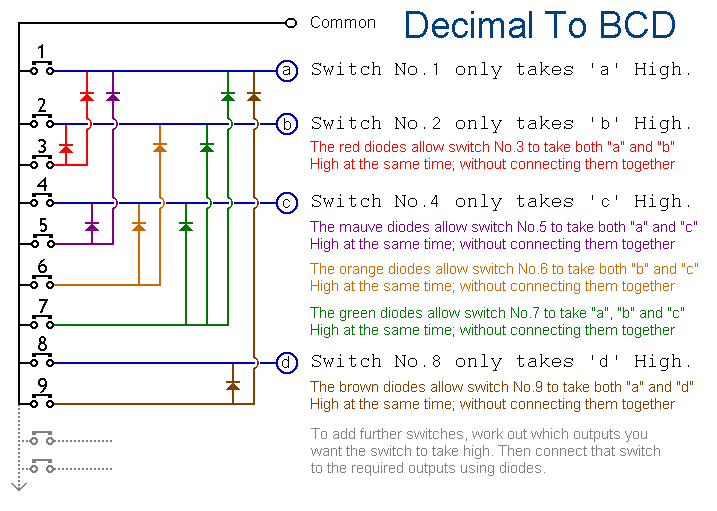
This circuit will provide an output in Binary Coded Decimal from any of the input switches. The input switches may be expanded to 16 switches, providing a Hexadecimal to BCD conversion.
Notes:
When any particular key is pressed, its value will appear in BCD form at the outputs (A, B, C & D). It will remain there until another key is pressed. The 12 keys produce outputs up to "1011". Extended to 16 keys, the circuit will give the full HEX to BCD conversion.
Memory Module:
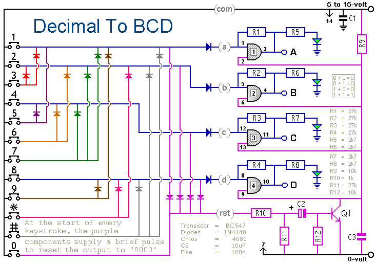
The above circuit produces an output ONLY while the input switch is depressed. To make a convertor with a latched output, the following modifications are made. Each CMOS 'AND' gate has its free input tied to Vcc, and by the action of R1 through R4 any 'hi input' will therefore cause the output to be latched.
When any particular key is pressed, its value will appear in BCD form at the outputs (A, B, C & D). It will remain there until another key is pressed. The 12 keys produce outputs up to "1011". Extended to 16 keys, the circuit will give the full HEX to BCD conversion.
The LEDs are a visual indication of the value. They are not necessary to the operation of the circuit. If you wish, you may leave them out; together with their associated resistors (R5, R6, R7 & R8).
The circuit works at voltages from 5 to 15 vdc. Please note that A, B, C & D are connected directly to the outputs of the Cmos IC. You will need to regulate the load your application places on these outputs.
Construction:
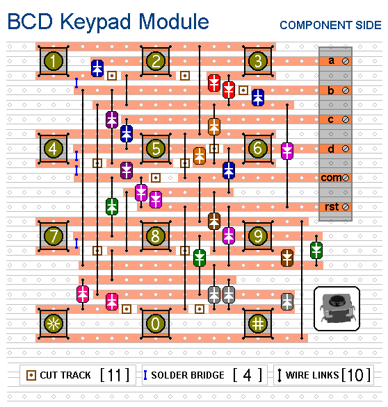
Because the keypad may be used without the memory, the layouts are drawn separately. If you build them both on the same piece of stripboard, isolate them from one another. Cut all of the tracks except for the six that join the keypad terminals to the memory module. Always check carefully that the copper is cut all the way through. Sometimes a small strand of copper remains at the side of the cut and this will cause malfunction. If you don't have the proper track-cutting tool, then a 6 to 8mm drill-bit will do. Just use the drill-bit as a hand tool; there is no need for a drilling machine.
Board Layout:
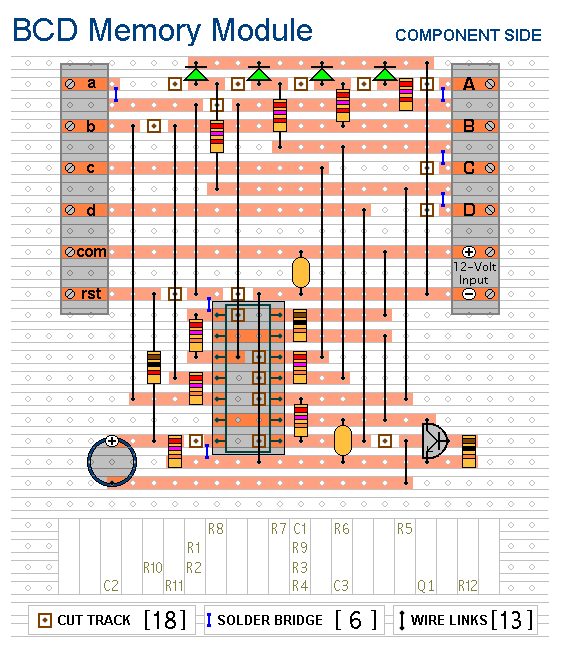
For clarity, all the components are shown lying flat on the board. However, those connected between close or adjacent tracks are mounted standing upright. Using a socket reduces the chances of damaging the IC; and makes it easier to replace if necessary. The links are bare copper wire on the component side of the board. Two of them need to be fitted before the IC socket. You can make the links from telephone cable:- the single stranded variety used indoors to wire telephone sockets. Stretching the core slightly will straighten it; and also allow the insulation to slip off.
Decimal to BCD Convertor
Circuit : Ron JEmail Ron
Description:
This circuit will provide an output in Binary Coded Decimal from any of the input switches. The input switches may be expanded to 16 switches, providing a Hexadecimal to BCD conversion.
Notes:
When any particular key is pressed, its value will appear in BCD form at the outputs (A, B, C & D). It will remain there until another key is pressed. The 12 keys produce outputs up to "1011". Extended to 16 keys, the circuit will give the full HEX to BCD conversion.
Memory Module:
The above circuit produces an output ONLY while the input switch is depressed. To make a convertor with a latched output, the following modifications are made. Each CMOS 'AND' gate has its free input tied to Vcc, and by the action of R1 through R4 any 'hi input' will therefore cause the output to be latched.
When any particular key is pressed, its value will appear in BCD form at the outputs (A, B, C & D). It will remain there until another key is pressed. The 12 keys produce outputs up to "1011". Extended to 16 keys, the circuit will give the full HEX to BCD conversion.
The LEDs are a visual indication of the value. They are not necessary to the operation of the circuit. If you wish, you may leave them out; together with their associated resistors (R5, R6, R7 & R8).
The circuit works at voltages from 5 to 15 vdc. Please note that A, B, C & D are connected directly to the outputs of the Cmos IC. You will need to regulate the load your application places on these outputs.
Construction:
Because the keypad may be used without the memory, the layouts are drawn separately. If you build them both on the same piece of stripboard, isolate them from one another. Cut all of the tracks except for the six that join the keypad terminals to the memory module. Always check carefully that the copper is cut all the way through. Sometimes a small strand of copper remains at the side of the cut and this will cause malfunction. If you don't have the proper track-cutting tool, then a 6 to 8mm drill-bit will do. Just use the drill-bit as a hand tool; there is no need for a drilling machine.
Board Layout:
For clarity, all the components are shown lying flat on the board. However, those connected between close or adjacent tracks are mounted standing upright. Using a socket reduces the chances of damaging the IC; and makes it easier to replace if necessary. The links are bare copper wire on the component side of the board. Two of them need to be fitted before the IC socket. You can make the links from telephone cable:- the single stranded variety used indoors to wire telephone sockets. Stretching the core slightly will straighten it; and also allow the insulation to slip off.
Return to Miscellaneous Circuits