Search for Science Fair Projects

1000 Science Fair Projects with Complete Instructions

Wire Temperature and Electrical Resistance

Wire Temperature and Electrical Resistance

Medium
Share this Science Project:
This page contains full project details. For the summary, please see the Project Summary.

Science Fair Project Description

This experiment was conducted to find out how temperature affects the conductivity and resistance of a wire. The experiment was done using copper wire of diameter 0.5 mm.
Complexity level:7
Project cost ($):20
Time required:1 hour to prepare, 1 hour for observation
Material availability:May be obtained from hobby stores, hardware supply shops, home depot etc.
Safety concerns:

Hypothesis

When the temperature of a wire increases, the resistance value of the wire will also increase and therefore the conductivity of the wire will reduce.

Overview

The resistance of a conductor is a measurement of the opposition to the current flowing in it. The value of the resistance will increase as the length of the conductor is made longer and the resistance will reduce when the diameter of the conductor is increased. The value of resistance is measured in ohms.

Electrical conductivity measures the ability of a conductor to allow current to flow in it. Therefore conductivity is the inverse of resistance.  The higher the resistance of the wire, the lower the conductivity will be.

Resistance   = 1 / Conductivity

Ohm’s Law states that when a current I ampere flows inside a conductor of resistance R ohms, the voltage V volt across the wire will be the product of the current and the resistance.

Voltage V = Current I x Resistance R
 

Scientific Terms

Conductivity, resistance, current, ampere, voltage, volt, ohm

Materials

The materials required for this science fair project:

-    5 meters of varnish insulated copper wire with diameter 0.5mm (may be purchased from hobby stores, motor rewinding workshops, etc...)

-    A PVC pipe about 300mm in length

-    Three 1.5V batteries and a casing to hold the batteries

-    3 jumper wires with crocodile clips at both ends

-    An ohm meter

-    An ammeter that can measure current  up to 10A

-    A paper knife

-    An infrared thermometer

-    1 roll of insulation tape

MEL Physics — monthly physics experiment kits delivered to your door. (Affiliate link)

See whats included

Procedure

1.    For this experiment, the independent variable is the temperature of the copper wire. The dependent variable is the resistance of the wire. This is determined by measuring the current and resistance of the wire. The constants (control variables) are the room temperature, the applied voltage, the diameter of the wire and the length of the wire.

2.    The wire of ? 0.5mm and length of 5 meter is wound around the PVC pipe. The ends of the wire are fixed to the pipe using the insulation tape. About 3 cm of insulation is removed from the wire tips using the paper knife. The resistance of the wire is measured using the ohm meter.

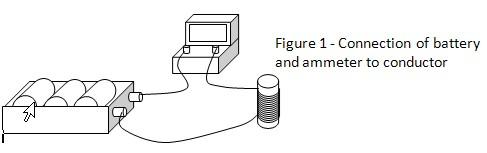
3.    The 3 batteries are connected in series to produce 4.5V. The ammeter, battery and wire wound around the pipe are connected as shown in figure 1. Connection is done using the jumper wires.
 

Electricity resistance science project

4.    The initial current reading shown on the ammeter is recorded in the table below. As the current flows in the magnet wire, the temperature of the wire will increase. This temperature is measured using the infrared thermometer. As the temperature increases 10°C, the ammeter reading is recorded, and the wire is disconnected from the circuit and the wire resistance is immediately measured using the ohm meter.

5.    The procedure 4 is repeated when the temperature of the wire increases every 10°C until the highest temperature reached and the measurements are recorded in the table below.
 

b1.jpgb2.jpgb3.jpg

Results

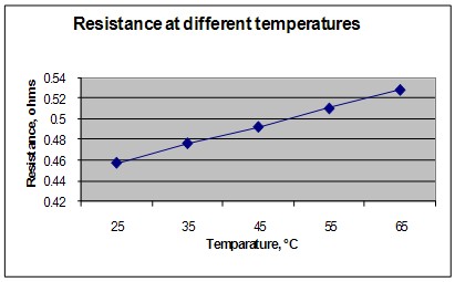
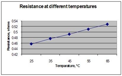
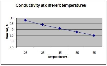
It is observed that as the temperature of the wire increases, the resistance of the wire also increases but the current flowing in the wire reduces.


Wire temperature °C

Voltage (Volt)

Current (Ampere)

Resistance (ohm)

25

4.5

9.82

0.458

35

4.5

9.43

0.477

45

4.5

9.12

0.493

55

4.5

8.80

0.511

65

4.5

8.50

0.529


The graph below represents the results of our science project experiment.

Resistance and conductivity science fair project
Temperature and electric currents science project

Conclusion

The hypothesis that when the temperature of a wire increases, the resistance value of the wire will also increase and  the conductivity of the wire will reduce is proven to be true.

The temperature of the wire increases due to its power loss, which is calculated as I2x R., where I is the current in the wire and R is the resistance. The higher the current in the wire or the higher resistance will cause the temperature of the wire to increase. Therefore it is important to choose the correct wire sizes to minimize this unwanted  loss and reduce the temperature of the conductor.
 

Also consider

What would happen if the experiment was repeated using different wire sizes?

The experiment can be repeated using aluminum wires.
 

References

Electrical resistance - http://en.wikipedia.org/wiki/Electrical_resistance

Electrical conductivity - http://en.wikipedia.org/wiki/Electrical_conductivity

Related videos

These videos explain the science behind this project and demonstrate key concepts used in the experiment.
Share this Science Project:

Related Science Fair Project Ideas

Soil Type, Fertilizer, and Electrical Conductivity
Insert copper electrodes into sand, clay, loam, and fertilized loam to discover which soil carries the strongest electrical current.
Medium
LED vs. Incandescent Brightness per Watt
Measure LED bulbs from 1.5 to 10.5 watts with a lux meter and find which tiny wattage matches a 60-watt incandescent bulb.
Medium
Hair Color and Static Electricity
Rub a balloon on four different-colored wigs and count paper squares to see which hair color builds the most static charge.
Medium